Session story · 2026-10-21
The manuals were readable, and the wiki was wrong
Session: 2026-10-19 03:07 → 2026-10-22 05:25 UTC (2026-10-18 20:07 → 2026-10-21 22:25 PDT; one conversation, mostly the evening of the 21st; the 2522 on the bench for one run) · a day of questions about how the instrument is reached, answered from the manuals that had been "garbled", then every IMD type on hardware, then a real receiver.
Where we started
The last session ended with real SMPTE IMD working from Cascade and a plan: probe the other IMD types the same way. Chris began by asking how that would work: ""Next session: probes for the other IMD types" - how will that probing work?" Three days later, the questions went wider.
The question
How does Cascade actually reach the instrument, and what do the manuals really say about it?
What happened
APIB is not GPIB. Chris: "using the documentation you have, can you tell whether the APIB interface is the same as a GPIB interface? what are the diffrences in how it is used". The GPIB manual answered plainly: on a System Two, GPIB is a factory option with its own firmware inside the instrument, which takes text commands and does the work itself. Over APIB the computer does all of it. That contradicted a memory note from June, which had called the two "alternate physical layers to the same instrument firmware". The note was corrected the same hour.
"what page is garbled? I can look at my copy" Claude had said the APIB wiring figure was unreadable. Chris offered to look it up, and the page turned out not to need him: rendered as an image, it was perfectly legible. Only its text layer was scrambled, by a font shifted 29 character codes. And it was a connection diagram, not wiring at all.
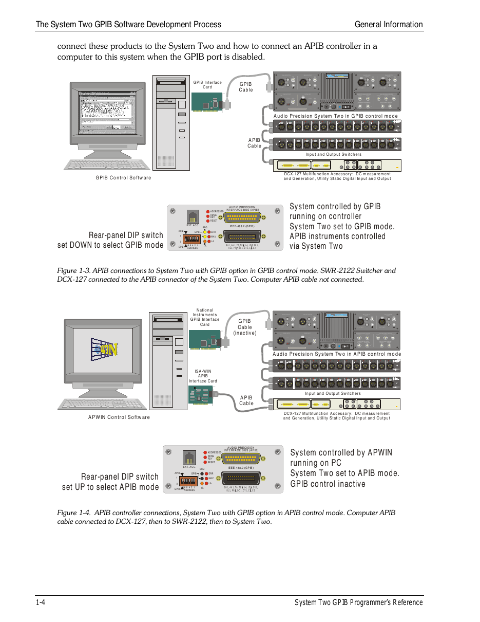
- 1 rear switch DOWN: GPIB in control
- 2 rear switch UP: APIB in control
- 3 in GPIB mode the APIB port drives the accessories
Every garbled page, from the images. Chris: "please do the same with other pages that are "garbled"". About 360 pages across four manuals had been summarised from scrambled text. Eight agents rendered each one and rewrote its summary from the picture. Almost everything was legible. They found the exact SMPTE low-tone list (40, 50, 60, 70, 100, 125, 250, 500 Hz), a pair of status bits recorded backwards, a tolerance value an earlier summary had invented, and about 60 keyboard shortcuts that had been guessed. Two agents shared a scratch folder and one ran the other's script by mistake; checking the two files it touched found them intact. What still cannot be read is now a short list: a formula printed in a broken font, a screenshot missing from the printed page, a few digits under arrows.
The wire, byte by byte. Chris asked for a page about the USB link, with a reason: "One of the reasons i am interested in this, is that there may be a way to make an APIB to Ethernet interface. Companies like Prologix have done this with GPIB controllers, for instance." Writing it turned up something new. The code had named the second byte of every register command a "module" since spring. Counting all 71,838 of them in a capture showed it is a width: one data byte or two, every time. The timings came from the same capture: about 100 µs per command that waits for a reply, and 85 % of them do. That is why a Prologix-style box is the hard case for APIB, and why the page recommends a small computer next to the instrument that keeps the waiting local.
All five IMD types. Then back to the bench. Chris: "ok build the probe". It replayed APWIN's own session one mode at a time and read the meter after each. Every reference level came within 0.3 % of APWIN's, and DIM 30, the mode a sine cannot fake, matched APWIN's raw reading to 0.1 %. Chris: "OK it's done . have a look for the latest log adn check". All five passed.
A real device, and a wrong number caught. Chris offered a test subject: "i have an old receiver that will have a lot of distortion and artifacts to measure." Claude described cabling that was not how Chris works, and was corrected: "this isn't quite how it works. banana plug + and - get converted to BNC for one channel. BNC to RCA. and then we use the RCA to XLR cables that came with the 2522 to plug into the 2522 input. that is how we always use the APWIN software." The receiver turned out to be a Scott 350R, and Chris tied it to an old request: "this is why i have asked so many times about getting the ground control - float, etc that APWIN has. it occasionally makes a difference". The APWIN manual's output diagram explained why: with the RCA cable, balanced grounded shorts half the output winding, and the useful choice is unbalanced floating or grounded.
Then a number. Claude had taken "500 mV maximum" for the AUX input from one wiki page and built limits around it. Chris: ""The AUX input tops out at 500 mV," are you sure about that? that wouldn't match most inputs - they are usually about 2V" — and then supplied the service manual. Its schematic settled it: the AUX path is passive all the way to the volume control.
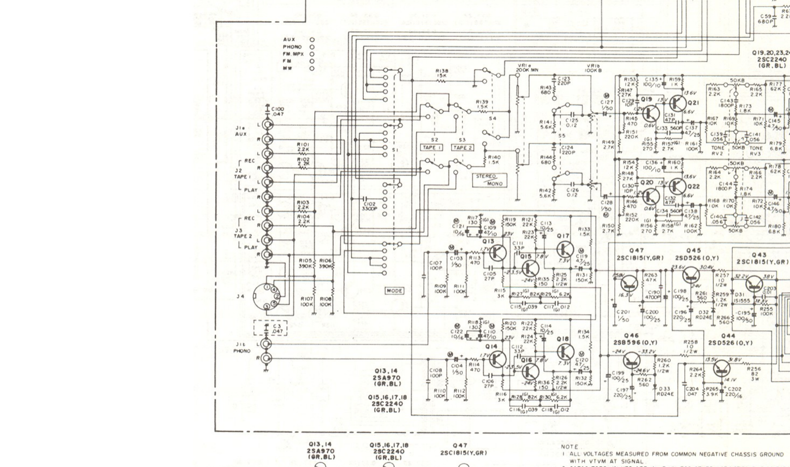
- 1 AUX input jacks
- 2 the volume control, VR1
- 3 first active stage, Q19/Q21
The plan was rewritten for unity gain, Chris's choice: "i think i will set it to unity gain. then the amplitude is mainly the 2522's job". A capture for APWIN on the same rig, T93, is written and waiting.
The turns
- APIB and GPIB are different control paths; the note that said otherwise was wrong since June.
- "Garbled" pages were readable all along, as images.
- A wiki's input limit lost to the receiver's own schematic.
Beliefs that changed
| Before | After | What changed it |
|---|---|---|
| APIB and GPIB carry the same commands | GPIB is an option with its own firmware; over APIB the PC does everything | The GPIB manual, pp.8–14 |
| About 360 manual pages were unreadable | Legible as images; about 20 items still open | Eight agents reading page images |
Byte 2 of 8A/EB is a module address | It is a data width | 71,838 commands counted in T92 |
| Real IMD worked in one mode | All five analog modes match APWIN | The all-modes probe on the 2522 |
| The Scott's AUX input tops out at 500 mV | AUX is passive to the volume control | The 350R service manual schematic |
What we learned about the instrument
- In GPIB mode the 2522 itself drives the APIB accessories; in APIB mode the computer does everything.
- Register commands carry a width byte; two-byte values are little-endian.
- A command that waits for a reply takes about 100 µs through the USB adapter.
- Every analog IMD type APWIN offers is reachable from Cascade, by replaying APWIN's own commands.
- The generator's output is a transformer; with an RCA cable, unbalanced is AP's intended setting.
What we learned about working together
- When a source is "unreadable", try another way to read it. The images were there all along.
- One source is a lead, not a fact. Chris's "are you sure about that?" led to the schematic.
- Ask how the rig is really wired. Chris's cabling is the one APWIN results were measured on.
Evidence
- Pages:
docs/story/apib.md,docs/knowledge/digest/UNCERTAIN.md,docs/bench_T91_T92_results.md. - Plan and capture:
docs/bench_receiver_plan.md,docs/T93_receiver_imd_config_v1.apb. - App session
session_20261021-185409(the all-modes probe). Commits: app 8662fbe; parent dd6619d … bba360a.
Where we ended
Every analog IMD type works from Cascade. The receiver is planned at unity gain, with a capture for APWIN ready for the PC. Next: run the plan, then use APWIN's readings on real distortion to calibrate IMD and build the ground control. Chris: "ok save this for later. i am disconnected for the day".